
Products

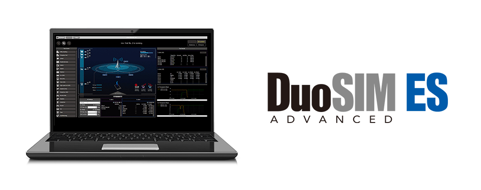
Built on the world’s most powerful platform for base station testing, the newest addition to the DuoSIM product line is here: The DuoSIM-5G delivers functional and performance testing for both gNodeBs and eNodeBs. Test for the future.
Elevate O-RU debugging with continuous capture of all O-RAN fronthaul IQ data. FH MONITOR boosts testing efficiency with comprehensive anomaly detection and analysis that ensures no issue goes unnoticed, even during extended test durations.
When problems and security breaches happen in your network, it’s already too late to start keeping records. The etherExtractor line of packet capture tools offers 0 packet loss and makes it easy to diagnose problems and analyze traffic across your network.
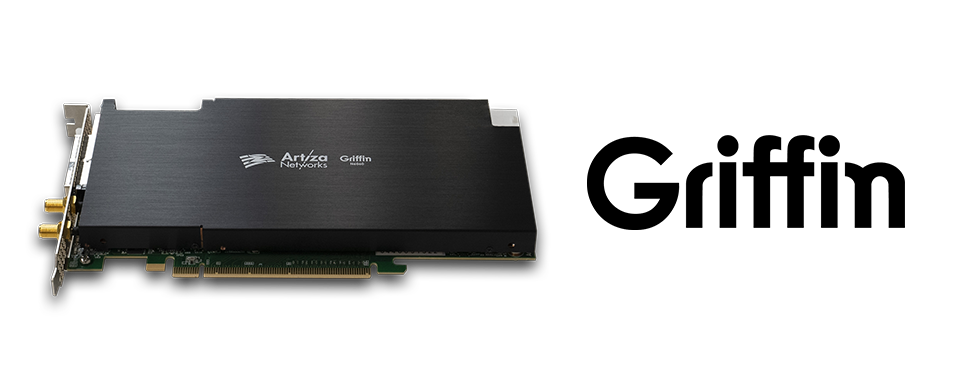
Equipped with an Intel® Agilex™ 7 F Series FPGA, the Griffin high-end FPGA board is ideal for accelerating vRAN functions and processing next-generation video using two on-board QSFP28 (100 Gbps).
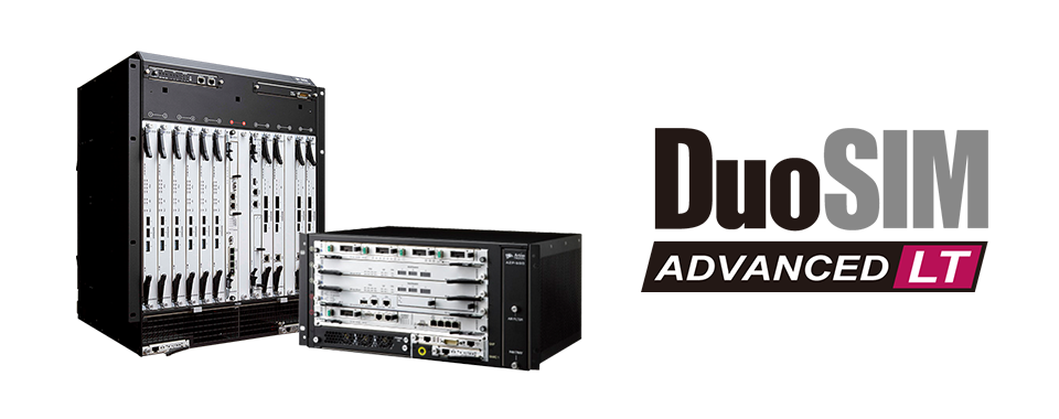
With unrivaled capacity and stability, the DuoSIM-Advanced Load Tester delivers a world-class performance testing solution with the lowest cost per UE in the industry.
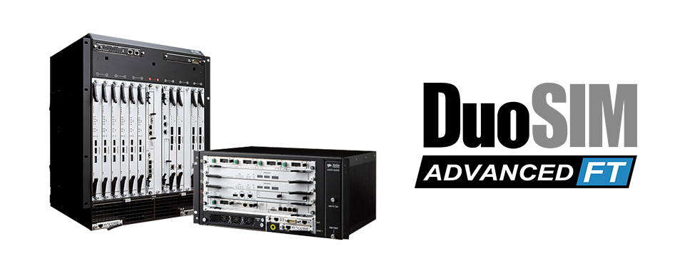
The DuoSIM-Advanced Functional Tester quickly validates new features, updates, and early stage development of LTE eNodeBs. It also scales up easily to match development teams’ changing needs.